IDE RAID 0 is not really considered a
true RAID since there isn't any data redundancy. RAID 0 takes two drives of the
same size/configuration and stripes them, meaning it makes one big drive out of
two equal ones. This improves performance by cutting hard drive latency in half.
Since the data is divided equally and written on two hard drives it also
increases the data bandwidth by two. The reason it's not considered true RAID is
because if one drive fails, all data is lost.
IDE RAID 1 on the other hand mirrors two
drives of the same size, so in theory if one drive fails, the other will take
over as the primary hard drive and the system can continue to operate normally.
This is what is supposed to happen with a SCSI hard drive setup and it actually
works pretty well there.
The IDE subsystem doesn't allow hard
drives to be disconnected while the computer is still powered up and in use like
SCSI can unless you have a special HDD tray. Generally, when one IDE drive fails
the system usually locks up anyway. The data is safe since it's mirrored on the
other drive which is the real benefit.
With IDE RAID 0+1, you need four
hard drives of the same configuration/size. What RAID 0+1 does is
stripes two sets of two hard drives, one set for a RAID 0 configuration and the
other for RAID 1. What this does is offer the best of both worlds, the high
performance of RAID 0, with 100% data redundancy of RAID 1. Hence the name RAID
0+1. The only downside would be the need for four identical hard
drives.
Around the Socket:
Heatsink Clearances
| pcstats
heatsink clearance measurements |
| top clearance: |
10 mm |
| bottom (cam) clearance: |
11 mm |
|
| left side (arm) clearance: |
9 mm |
| right side clearance |
26 mm |
|
| socket mounting holes: |
4mm ødia. |
| max. heatsink base dimensions: |
~85x90 mm |
|
 Note: Approx.
measurements are made from the edge of the socket (not the clips) to
the closest obstacle taller than the ZIF socket
itself. Note: Approx.
measurements are made from the edge of the socket (not the clips) to
the closest obstacle taller than the ZIF socket
itself.
The socket is 51mm across, and 62mm from
top to bottom. | |
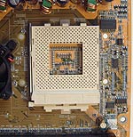 |
The space around the CPU socket is mediocre at best, and unfortunately
the left side of the CPU socket is very close to the
clipping mechanism of the chipset fan so installation of larger heatsinks such as the
Swiftech MC462A or Alpha PAL8045 might not be possible.
Also, wider heatsinks might have a hard time
fitting on this motherboard as well. We measure the distances around the
socket so you can figure you for yourself if a particular heatsink will fit,
so please have a look at the chart above.