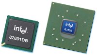
Meet the E7205 Granite Bay Chipset

Dual DDR for the
Pentium 4 was the final stake that killed the relationship between Intel and Rambus.
Remember back two years ago when the Pentium 4 was first released, you could only
use it with extremely expensive RDRAM?
The P4 wasn't
selling well and Intel finally caved to public pressure and released the original i845
which was a SDRAM chipset for the Pentium 4. Obviously, we have heard enough
performance horror stories about SDRAM + P4's and soon enough, the i845D evolved to use DDR
and the rest is history.
However one problem with the i845 chipsets were they could never provide
quite enough bandwidth to keep a P4 running at full potential, and this is where the
E7205 Granite Bay chipset comes in.
"Why does Granite Bay only support
PC2100 DDR and not PC2700?!?" I get that question a lot
from readers. The reason behind this is that Granite Bay runs it's memory in parallel, thus doubling
the bandwidth available to the processor from 2.1 GB/s to 4.2 GB/s.
4.2GB/s is exactly the bandwidth requirements
a Pentium 4 running on 533 MHz FSB needs. Giving the processor more bandwidth is a
waste of resources and will not net you any real performance gains. For example, consider what RDRAM or DDR
RAM does for a Pentium III or DDR333 for 266 MHz based Athlon's!
Granite Bay is also
the first Intel chipset to support 8x AGP.
8x AGP doubles the bandwidth available to the videocard from
1.06 GB/s (4x AGP) to 2.1
GB/s. This means that twice as much information can reach the videocard at
any given moment, however so far we haven't seen much benefit for 8x AGP videocards as of
yet.Because the GNB MAX is intended mainly for workstation use, MSI have opted to equip
the board with an 8x AGP Pro slot.

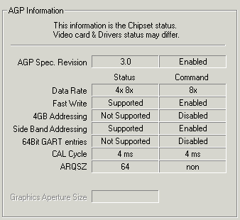
As
you can see 8x AGP was working just fine with the ATi Radeon 9700
Pro
The board
we were sent for testing was an engineering sample, and so there was one minor
issue which was some apparent undervolting in the BIOS. A P4 2.8 GHz processor at
stock speeds requires a specified voltage of 1.525V, and according to the BIOS, the unit we
tested was only supplying 1.45V or so. Of course since this
test unit was an engineering sample and I'd expect MSI to have the bug fixed in their retail
boards.

Serial ATA / IDE RAID
Explained
IDE RAID 0 is not really
considered a true RAID since there isn't any data redundancy. RAID 0 takes two
drives of the same size/configuration and stripes them, meaning it makes one big
drive out of two equal ones. This improves performance by cutting hard drive
latency in half. Since the data is divided equally and written on two hard
drives it also increases the data bandwidth by two. The reason it's not
considered true RAID is because if one drive fails, all data is lost.
IDE RAID 1 on the other
hand mirrors two drives of the same size, so in theory if one drive fails, the
other will take over as the primary hard drive and the system can continue to
operate normally. This is what is supposed to happen with a SCSI hard drive
setup and it actually works pretty well there.
The IDE subsystem doesn't
allow hard drives to be disconnected while the computer is still powered up and
in use like SCSI can unless you have a special HDD tray. Generally, when one IDE
drive fails the system usually locks up anyway. The data is safe since it's
mirrored on the other drive which is the real benefit.
With IDE RAID 0+1, you
need four hard drives of the same configuration/size. What RAID
0+1 does is stripes two sets of two hard drives, one set for a RAID 0
configuration and the other for RAID 1. What this does is offer the best of both
worlds, the high performance of RAID 0, with 100% data redundancy of RAID 1.
Hence the name RAID 0+1. The only downside would be the need for four identical
hard drives.
|
