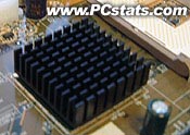
The thing that bothered me the most is not that DFI chose
to go with a passive heatsink to cool the KT400 chipset, rather that they attached the
heatsink with thermal glue! If the previous VIA KT chipsets are any indications,
the KT400 will get quite toasty when in operation, and it would have been nice to
have some better form of cooling on the Northbridge.
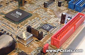
I'm not sure why DFI had to include so many
little blue jumpers. Couldn't they just incorporate things like 100/133/166 MHz FSB adjustments in
the BIOS? The ATX power connector is to the right of
the CPU socket and just on top of the AGP slot which will interfere with the CPU
fan but I understand that this supplies cleaner voltages to the MOSFETs. I'm sure you all
know my feelings towards AC'97 based sound cards.
Serial ATA / IDE RAID
Explained
IDE RAID 0 is not really
considered a true RAID since there isn't any data redundancy. RAID 0 takes two
drives of the same size/configuration and stripes them, meaning it makes one big
drive out of two equal ones. This improves performance by cutting hard drive
latency in half. Since the data is divided equally and written on two hard
drives it also increases the data bandwidth by two. The reason it's not
considered true RAID is because if one drive fails, all data is lost.

IDE RAID 1 on the other
hand mirrors two drives of the same size, so in theory if one drive fails, the
other will take over as the primary hard drive and the system can continue to
operate normally. This is what is supposed to happen with a SCSI hard drive
setup and it actually works pretty well there.
The IDE subsystem doesn't
allow hard drives to be disconnected while the computer is still powered up and
in use like SCSI can unless you have a special HDD tray. Generally, when one IDE
drive fails the system usually locks up anyway. The data is safe since it's
mirrored on the other drive which is the real benefit.
With IDE RAID 0+1, you
need four hard drives of the same configuration/size. What RAID
0+1 does is stripes two sets of two hard drives, one set for a RAID 0
configuration and the other for RAID 1. What this does is offer the best of both
worlds, the high performance of RAID 0, with 100% data redundancy of RAID 1.
Hence the name RAID 0+1. The only downside would be the need for four identical
hard drives.
If you'd like a bit of information on the VIA KT400 chipset,
please read our MSI KT4 Ultra-FISR review.
Around the Socket:
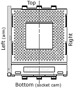
Heatsink Clearances
| pcstats
heatsink clearance measurements |
| top clearance: |
14 mm |
| bottom (cam) clearance: |
7 mm |
|
| left side (arm) clearance: |
16 mm |
| right side clearance |
20 mm |
|
| socket mounting holes: |
4mm ødia. |
| max. heatsink base dimensions: |
~83x94 mm |
|
 Note: Approx.
measurements are made from the edge of the socket (not the clips) to
the closest obstacle taller than the ZIF socket
itself. Note: Approx.
measurements are made from the edge of the socket (not the clips) to
the closest obstacle taller than the ZIF socket
itself.
The socket is 51mm across, and 62mm from
top to bottom. | |
|
Another thing that we were happy to see was
that DFI has included the four surrounding mounting holes even though AMD has
taken them off their requirements list. There is a good amount of space around the
CPU socket so you shouldn't have any problems installing larger heatsinks like the
Alpha PAL8045.
Overclocking the
AD77
DFI have been focusing on areas which don't
always mean that enthusiasts get what they would call "overclocker
friendly" features and tools. There is a lot of competition in the relatively
small enthusiast market, so this doesn't always make too much sense from a
manufacturers perspective - but since enthusiasts are often gammers, the
two do go hand in hand on some points (performance namely).
We were pleasantly surprised to see how many
overclocking options the AD77 Infinity had, perhaps DFI are going to
be focusing more on overclockers this year as a price war is expected
to hit the motherboard market shortly.
We ran into some weird problems when it came to overclocking
the AD77 Infinity however. With the original BIOS the board was shipped with we
had no problems running at 190 MHz FSB - however once we flashed the board
with the latest BIOS, we could no longer overclock. The options were still there,
but the board simply refused to boot into Windows if we ran the board at 5 MHz FSB
higher then stock (166 MHz FSB was our starting point since we're using an
AthlonXP 2700+).
We're not really sure what the problem was
and every time I tried flashing the board back to the original BIOS, it would just hang. This may have
been isolated to the board we received for testing, and as we already mentioned,
with the BIOS it shipped with overclocking was fine.
