The IS7-G
uses a simple redish-brown coloured PCB that
skips the whole blinking LED fad (thankfully) in favor of a
clean, uncluttered layout
and northbridge cooling fan. In general Abit motherboards are pretty well laid out,
and the IS7-G is no exception to that rule. From a users
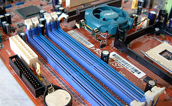
standpoint it is nice to see the main ATX and floppy drive connectors located to the right
of the DIMM slots where they are also easy to get
at.

Because
the Pentium 4 processor gets
its power from the 12V line we were not surprised to see the ATX12V connector next
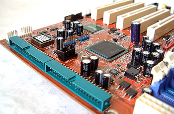
to the MOSFETs. The IDE connectors are positioned on their sides at
the edge of the board where they will give more clearance to longer PCI devices. With the
IDE cables laying flat, the airflow at the front of the case is
less likely to be obstructed as well.

 With so many USB devices on
the market and with more coming out, we were glad to see Abit places four
USB 2.0 ports on the rear I/O panel.
As with other Abit motherboards in the past, the
IS7-G is very well labelled all over.
The onboard 3Com Marvell Gigabit Ethernet adapter
runs through the PCI bus, but we understand that the IS7-G is aimed at the
mainstream market and so most users will probably not be in a position to see a
slow down.
We were
able to obtain the "PAT enabled" BIOS for the IS7-G and test it out quickly.
That BIOS version really did improve the overall performance of the system.
For example, stock 3DMark scores went up from 16.1k to just over 16.5K, and bandwidth
increased as well!
However, since the PAT
enabled BIOS is a beta version and not available to the public (as of June 13th,
2003) we did not use it in our testes. Instead we used
the original BIOS release for the motherboard.

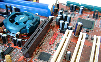
I was a bit surprised to see the one big 6.3V
2200µF capacitor sitting just right next to the first PCI slot. If you're
using a longer PCI cards you may have problems installing it in PCI slot
one. The reset CMOS jumper is in a bad location just above the main ATX power
connector. With the motherboard installed in a case you'd probably have to
remove the ATX power connector to get to the jumper should you overclock too
high.
The DIMM
slots are packed in closely together... which presents a curious situation because there is virtually no space
between heatspreader encased DIMM's. Considering the amount of motherboards which have DIMM slots right
up against one another I'm somewhat surprised that the effect this will have on heatspreader encased memory
modules has not been considered. With DIMM slots like this, the facing sides
of DDR with a heatspreader are completely insulated from just about all convection
cooling.
It would be nice if Abit could place the two IEEE 1394
connectors elsewhere. Where they are the cables will run directly in front of
the GPU HSF... and you all know how particular I am about my
videocards.For those of you who are
interested in learning about
i865PE technology please read PCstats' review of the AOpen AX4SPE Max motherboard.
