
|
In this Beginners Guide PCSTATS aims to give you a
basic visual acquaintance with the various ports and connectors on your PC, and a general understanding of what they are and how they work, hopefully bridging a circuit between the jargon and your hands-on knowledge of your own computer.
|
|
|
|
Home >
Reviews >
Beginners Guides >
Beginners Guide |
|
|
Firewire, PCI, Videocard, CPU, etc.
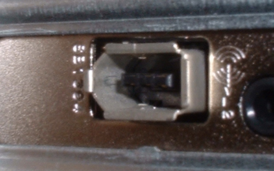
FireWire (IEE1394) connector: A
high-speed external connection standard similar to USB. FireWire was developed
by Apple, who still hold the trademark to the term. It is, however a standard
(IEE1394) so other companies can develop products based on it. Like USB,
firewire connectors are hot pluggable, support plug and play, and can provide
power to devices. There are two different versions, 1394a and 1394b, capable of
400Mbps and 800Mbps data transfer rate respectively. Extensively used by Apple
for the Mac computer line, and initially popularized as an excellent way of
transferring video footage (which requires a huge amount of data throughput)
into a computer for editing, FireWire has remained somewhat of a niche product,
never achieving the popularity or the installed base of USB products. A firewire
controller can theoretically support up to 63 devices.
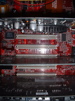
PCI slots: Internal connectors
for attaching expansion cards such as video adaptors, sound cards or network
cards to the motherboard. PCI stands for Peripheral Component Interconnect. PCI is
the current standard for PC expansion cards, and looks set to remain this way in
the future, though some measures have been undertaken to increase the
data-handling capacity of the PCI bus, resulting in PCI-X, a compatible version
with much increased data throughput. This is necessary for handling demanding
expansion cards such as gigabit (1000base-T) Ethernet cards which would
ordinarily be held back by the slower data transfer rate of regular PCI ports.
The vast majority of modern motherboards only use regular PCI slots though, and it
will likely stay this way for a few years at least. PCI is plug and play
compatible, allowing a PnP compliant operating system to automatically detect a
new device attached to a PCI port and install drivers if available. The computer
must be turned off in order to install a PCI device.
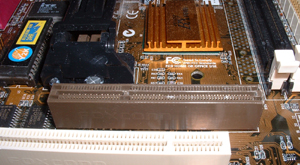
AGP (Accelerated Graphics Port):
An internal connector used to attach a graphics adaptor (video card) to
the motherboard. With the rise of 3D graphics accelerators to render the
increasingly realistic 3D graphics of modern games, it became apparent that the
PCI bus was not sufficient to handle the amount of information that needed to be
passed between the main memory and the video card. Video cards with built in
Graphics processors and memory could perform many of the complex calculations
necessary to render three dimensional images by themselves, taking some of the
load off the processor, but a tremendous amount of information still needed to
be sent every second, and as the capabilities of the video cards increased, so
did the demands of the software (read 'games') built for them. The solution to
this was the AGP bus, which provides an increased data transfer rate, along with
a more direct path to the main memory. AGP was adopted rapidly by the industry,
and is now an integral part of every modern motherboard. It comes in successive
versions, each with increased data transfer speeds. AGP 1x, 2x, 4x and 8x. A
higher rated port will work with a lower rated card, but the opposite is not
recommended. As with PCI connectors, AGP supports plug and play, and the
computer must be off to install a new device. Note that computers with AGP
connectors can still use PCI graphics cards.
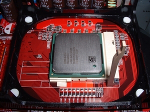
CPU socket/slot: The socket
that connects the processor to the motherboard. These come in a variety of forms,
depending on the range of processors they are designed to work with. All recent
processors use the ZIF (Zero Insertion Force) socket design, which uses a lever
to open the socket for insertion of the CPU, then closes the lever to lock it in
and connect the CPU to the motherboard. They will also generally include clips for
attaching heat sinks to the socket/CPU. Older boards may use Slot designs, in
which the processor comes mounted on a small circuit board of its own, and is
inserted into the slot and clipped down, similar to memory chips, though much
larger. Recent socket types are socket 462 for AMD Athlon XP and Duron
processors, socket 478 for Intel Pentium 4 processors, and socket 370 for older
Intel Pentium 3 processors and VIA C3 processors. Intel Pentium 2 and early
Pentium 3 processors used a slot design.
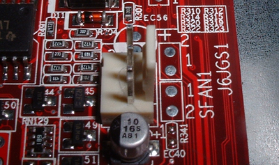
Motherboard fan headers: 3-pin
plugs on the motherboard for powering internal fans. Modern motherboards will likely
have several.
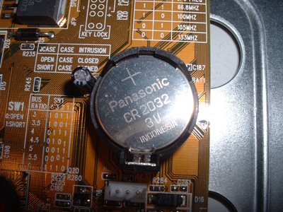
CMOS battery: The CMOS (or
Complimentary Metal Oxide Semiconductor, don't worry, you will not be required
to remember that for the test.) is a small area of memory which holds the
dynamic information that the motherboard needs. Date and time are kept there, as
well as any changes made to the BIOS, or basic settings of the board. To
maintain this information, the CMOS needs a constant trickle of electric
current, provided by a small battery. This battery (generally a CR 2032 on all
modern boards) will last several years on average. If it fails, or is
disconnected, the BIOS will be reset to the default constantly, which may or may
not affect the running of the computer.
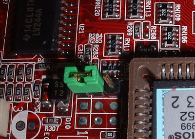
Motherboard Jumpers: Though
modern motherboards are several giant leaps ahead of the boards of 5 years back or
so, when many settings needed to be configured manually on the board before it
could be used, they still retain at least a few manual jumper switches for
certain operations. A jumper switch is simply two metal pins that can be bridged
with a cap (or jumper) to form a circuit. No jumper, no circuit. The most common
example of this present on modern motherboards is the jumper for clearing the CMOS
settings, otherwise known as resetting the BIOS, or basic settings, of the
motherboard. Generally found very near the CMOS battery (consult your motherboard
manual), if this jumper is bridged and the machine turned on, the CMOS will be
erased and the board settings reset to their defaults. Note that the jumper will
need to be unbridged again before turning the machine back on. In general,
changing jumper switches should always be done with the computer powered off.
More ports and connectors on the next
page...
|
< Previous Page
|
© 2025 PCSTATS.com
Please respect the time and effort that went into creating each PCSTATS Beginners Guide, do not illegally copy. Thank you.
|
Next Page >
|
|

